
- Like
- Digg
- Del
- Tumblr
- VKontakte
- Buffer
- Love This
- Odnoklassniki
- Meneame
- Blogger
- Amazon
- Yahoo Mail
- Gmail
- AOL
- Newsvine
- HackerNews
- Evernote
- MySpace
- Mail.ru
- Viadeo
- Line
- Comments
- Yummly
- SMS
- Viber
- Telegram
- Subscribe
- Skype
- Facebook Messenger
- Kakao
- LiveJournal
- Yammer
- Edgar
- Fintel
- Mix
- Instapaper
- Copy Link
If you’ve built a version of this rack design I’d love to add a picture or two to this gallery. To be included send a few pictures and info for a caption (description, location, profound revelation, whatever) to don_alejandro at spectrumz dot com.
Click any image to view at full size
-
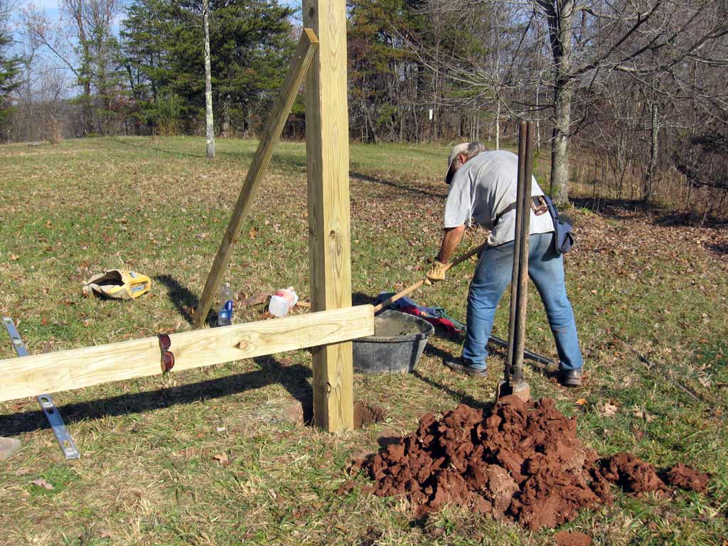
- Be sure the poles are vertical and aligned in the same plane before mixing concrete. We temporarily screwed a 2×6 between posts to be sure the flat surface of posts are aligned in the same plane.
-

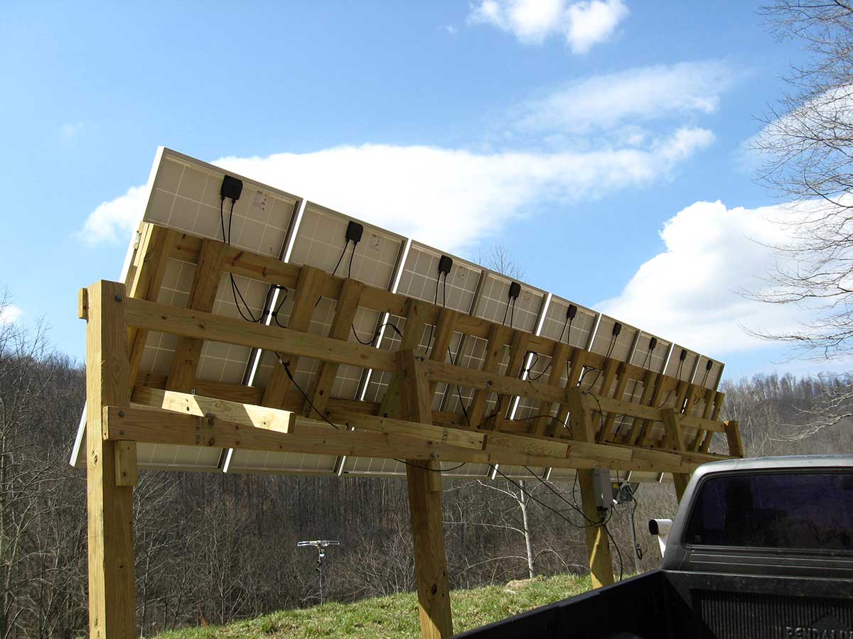
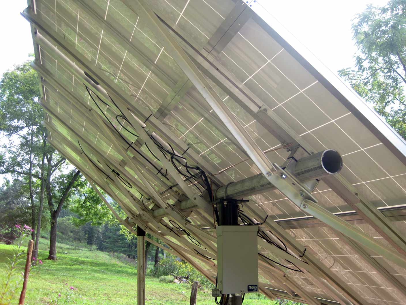
- Back view of our panels showing better detail on the adjustment arms.
-
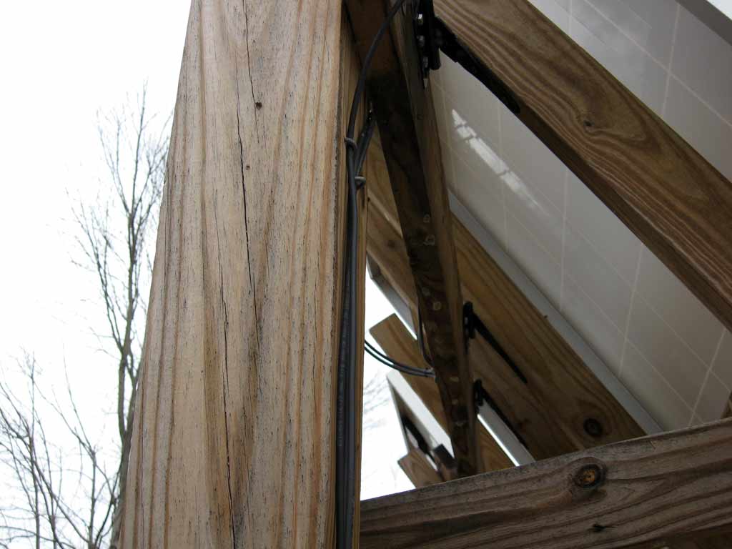
- Close up the hinges
-
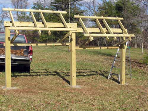
- Racks ready for panels
-
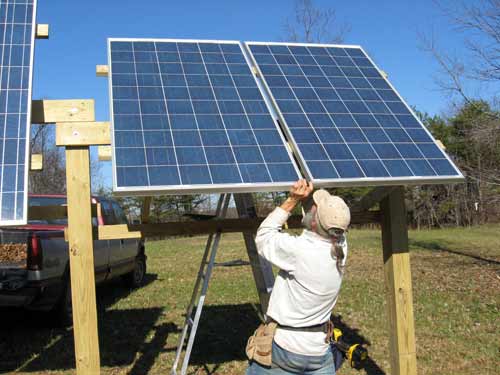
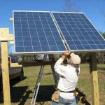
- Attaching the panels
-
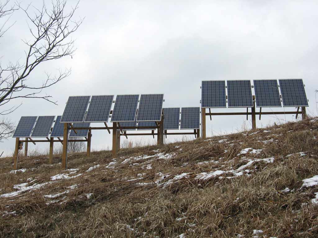
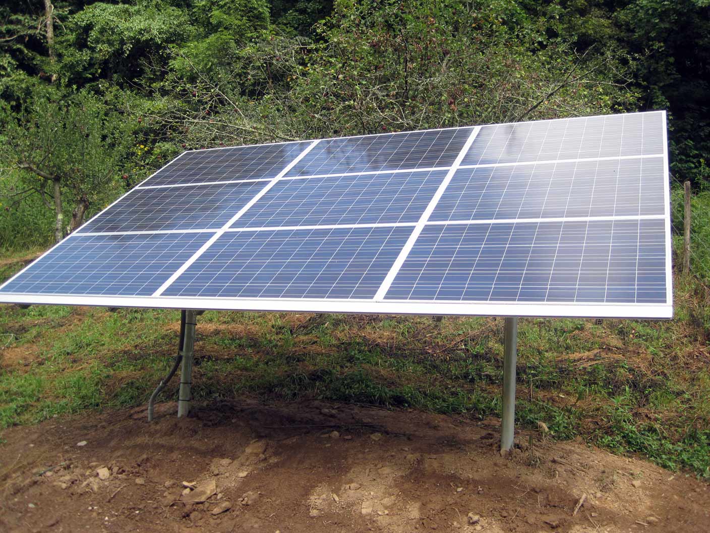
- Our neighbor’s 16 panels, mounted in groups of four.
-
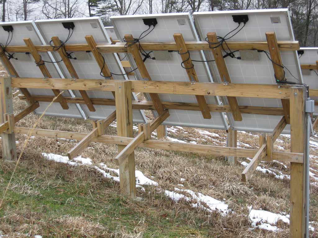
- One of our neighbors racks from behind. He laid the vertical pieces sideways to allow using a wider hinge
-
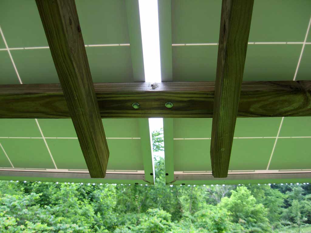
- Close up of panel mounting bolts
-
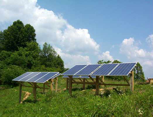
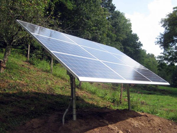
- Neighbor’s panels adjusted for summer.
-
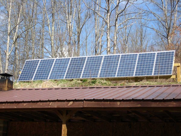
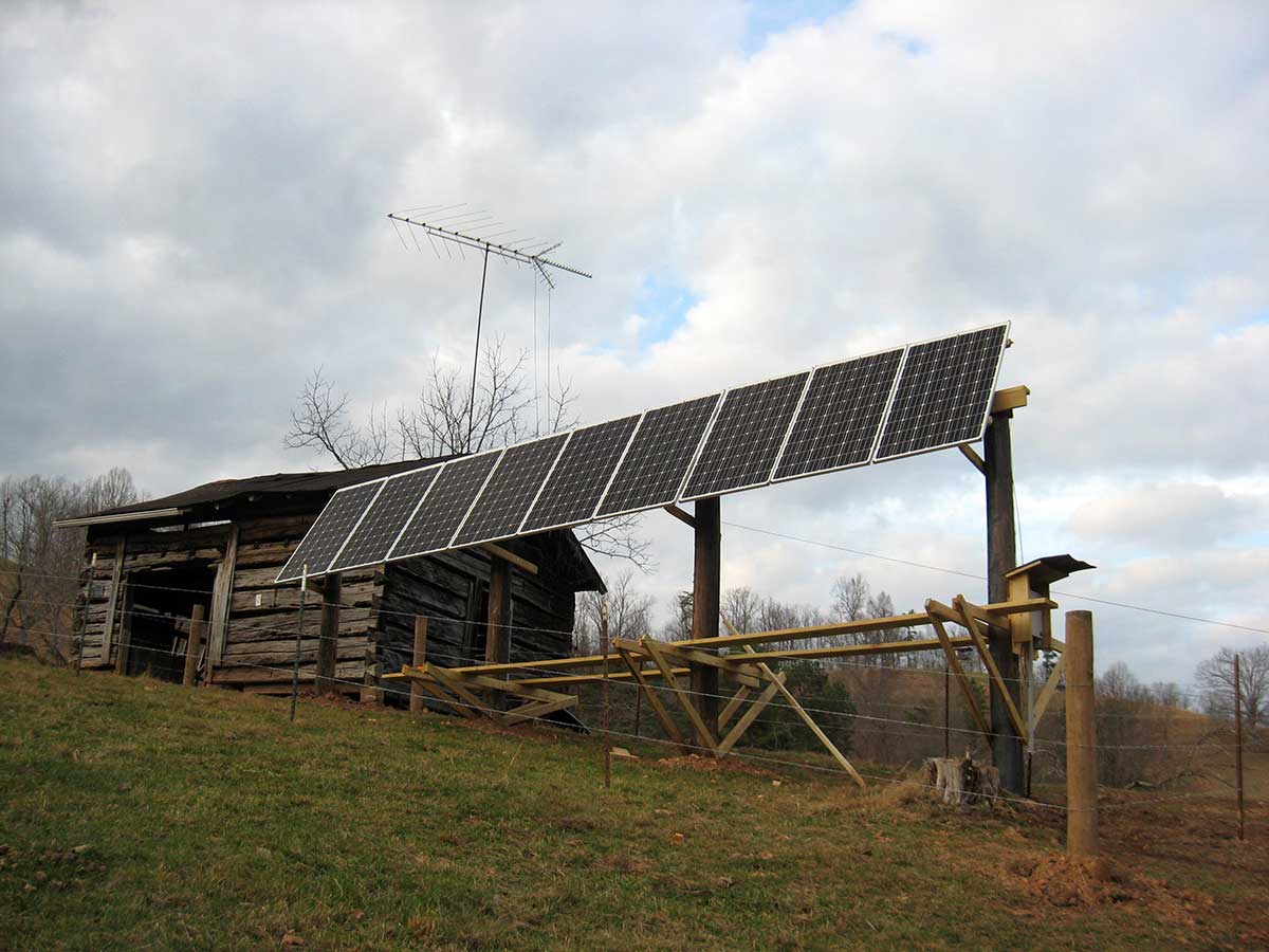
- The same basic design modified for 9 panels in a straight line over an underground house in WV. These were modeled after a 20 panel rack-set that was modeled after our neighbor’s 16 panel set that was modeled after our original 4 panel rack.

-
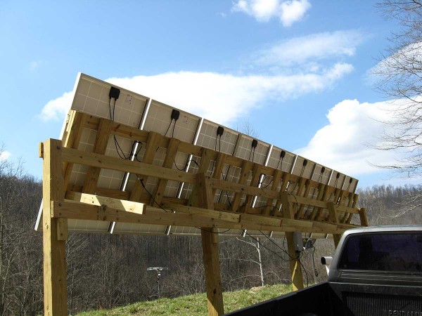
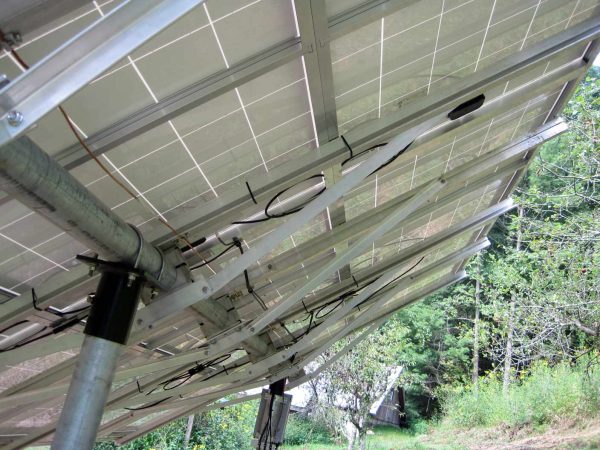
- Behind the 9 panel rack
-
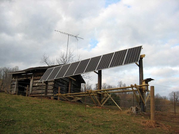
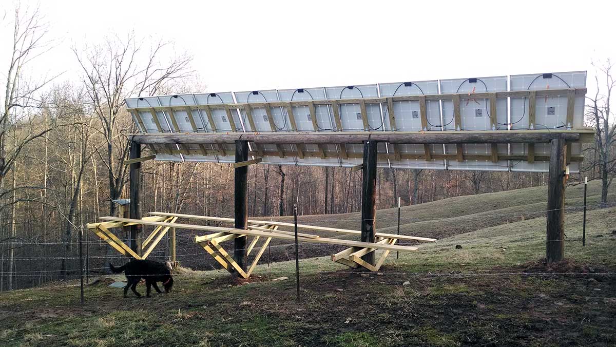
- Another 9 panel installation near Spencer WV
-

- Back side of second 9-panel array, built with stout poles rather than 6×6 posts.
-

- Metal solar panel rack design inspired by the wood rack
-
- Metal solar panel rack design inspired by the wood rack

-

- Back side of metal rack
-
- Back side of metal rack

Hi Don,
I’m in the process of building a treated lumber ground mount rack like your design. I’m using 6×6 posts. What was your process for setting the treated posts in the ground? Did you use concrete or gravel or both? I’ve heard of people pouring the dry redi-mix in the hole and then adding water. Have you heard of this being done? Thanks in advance for any words of wisdom.
Any of those methods should work okay. I used ready-mix concrete, which I mixed with water before filling post holes, though I have heard of people setting poles by pouring in the dry mix (satellite TV and internet installers usually do that).
A friend of mine used finely crushed gravel to set his poles (called ‘crusher run’ at our local rock yard). He made his post holes a little deeper (3 feet) and a larger diameter than necessary for concrete (8-10 inches clearance on all sides of the post). One advantage of this method is that you can put the post in place and gradually add and tamp crushed gravel (while a helper holds the post) so that you can make minor adjustments to the post position to be sure it’s vertical and in alignment with the other poles (the poles should be aligned in a a plane). With concrete you have to align the poles and attach temporary braces to hold them in place while the concrete sets.
I followed your design quite closely for 12 x 285 w panels. Because we are in a high snowfall area at 4600 ft above sea level, I mounted the panels horizontally to reduce the risk of a small amount of snow causing the shutdoown of a complete panel instead of one or two rows. So far so good. We will be relying on back up charging as our daylight reduces to an average of 5 hours max during winter months and poor weather. I did build the panel array out of pressure treated wood for about 40 % of the cost of a metal support structure. We’re very happy to be able to flick a switch for lights. Selling old propane lights and should recover half the cost of the wooden structure.
I’m currently looking for a design for my setup , I have 10 100 watt solar panels , I bought them at CANADIAN TIRE in CANADA . They were on sale at 65% off of a box of two . I live in eastern Ontario , Sharbot Lake. I like what you have done , it is just about the same as what I was thinking . I want to build this stand about 80 ft from the house , do you have any suggestions as to what size wire to buy . I noticed the wires on the panels are of alluminum I am not aware if alluminum is available here . It was used in the seventies for a time . Any help you can offer is greatly appreciated.
Most solar panels I’ve seen have a short cable of copper wire with a connector, which is usually plugged into a mating connector that uses copper wire to connect to a combiner box (at the panels) containing circuit breakers or fuses. A cable runs from the combiner box to the charge controller electronics (in your house). If you have unusual panels with aluminum wire, be sure to use an anti-corrosion paste on connections at your combiner box.
You can use either copper or aluminum wire between the panels and your house, but the size depends on the distance and expected current. For example, if you have ten panels that each produce 10 amps at 24 volts, you could connect them in parallel or series, or some combination of parallel and series. Ten panels in parallel would produce 100 amps at 24 volts. Ten panels in series would produce 10 amps at 240 volts. Ten panels with five sets of two parallel panels in series would produce 20 amps at 120 volts. You would need much larger wire size to run 100 amps at 24 volts, and the voltage drop in the wire (100 amps times the resistance of the wire) would be a significant percentage of the 24 volt (a 2.4 volt drop out of 24 volts would waste 10% of the total power). The wire size needed for 10 amps at 240 volts is much smaller, and the voltage drop (10 amps time wire resistance) would be a much smaller percentage of the total power – a 2.4 volt drop out of 240 volts would only waste 1% of the power). This is why transmission lines run at high voltage.
Of course, you need a charge controller able to handle whatever input voltage you use. We have four 24 volt panels, two panels in parallel connected in series with another two parallel panels, nominally producing 20 amps at around 52 volts in full sun (the open circuit/no load voltage is about 70 volts, and our charge controller can handle up to 150 volts). Our panels are only about 20 feet from the house, connected by 4ga copper wire between the combiner box and charge controller.
One of the people who used this basic rack design put his panels on top of a hill a couple hundred feet from his house. He put nine panels in series (nominal 216 volts at 10 amps, maximum 315 volts in full sun with no load) – I think he used 10ga or 12ga copper wire – since the maximum current is fairly low (10 amps) the voltage drop in his long run is less than 4 volts, which is less than 2% of the total power. Of course, he had to purchase a charge controller capable of handling a high input voltage.
How did you attach the panels to the wood?
The image above labeled ‘Close up of panel mounting bolts’ show bolts going through 2×4’s and mounting holes on the underside of the aluminum panel frame, secured by lock-washers and nuts (click on the image for a larger view).
I’m local to your area and am in the planning stages of erecting this structure and am concerned about the effect of very high winds (like we had a couple weeks ago) ripping the panels off the mount; have you had any problems like that?
No problem with wind – everything is screwed together with nuts and bolts…
I’m liking your design and have adapted it for my situation, Augusta Maine area, 6 panels, 195 watts each, wired in series, not far from house. My question is, when you mount the panels to wood, is it necessary to ground them in case of lightning strikes. Typically, I notice solar panels are mounted on aluminum frames bolted to metal poles buried in the ground. Should I wire all the panel frames together and then drive a piece of re-bar into the ground and then clamp the ground wire to the re-bar? My combiner box has a connection for ground, perhaps that is sufficient?
I’d recommend a genuine copper-clad ground rod for the earth ground. Our panels have an aluminum frame – I connected the frames with wires, and connected them to the earth ground at the combiner box.