Wiring diagram showing the internal wiring of the telco filter block. The wires for the phone and modem can be in the same cable (i.e., red/green, yellow/black), but they must connect to the center two pins of their respective modular jacks in the shack. Phone cable or CAT cable with twisted pairs of wire is preferable to non-twisted multi-wire cable or flat phone cables.
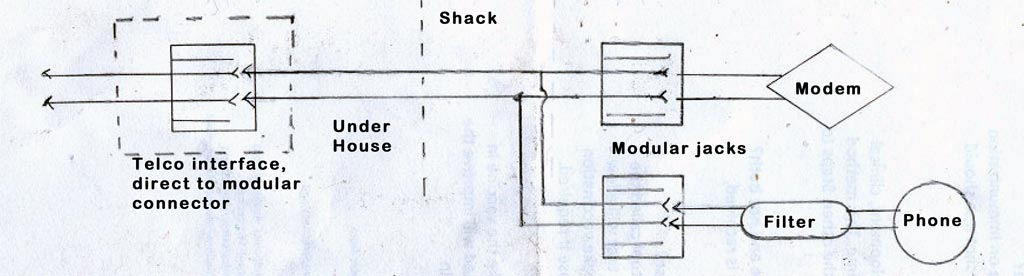
Wiring diagram utilizing a direct connection to the modular jack in the telephone interface box. A single twisted pair running to the center pins of two modular jacks. The dsl filter is sort of optional, especially if the phone is not used much, though connecting to too many phones without using the filter can degrade the dsl signal, especially if one or more phones are off-hook. The filters also eliminate DSL noise from the phone (for people who can hear it).
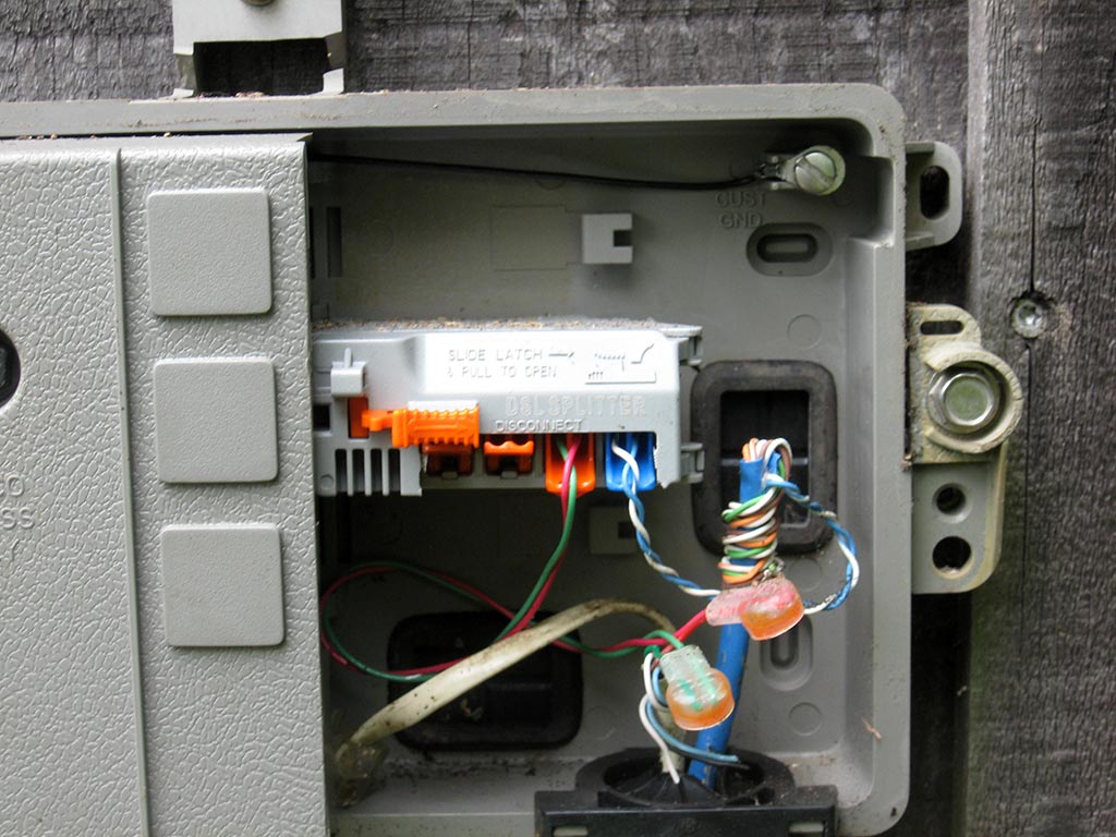
Filter/connector block currently installed in my telephone ‘line subscriber interface box’ (also sometimes called the ‘network interface’ box).
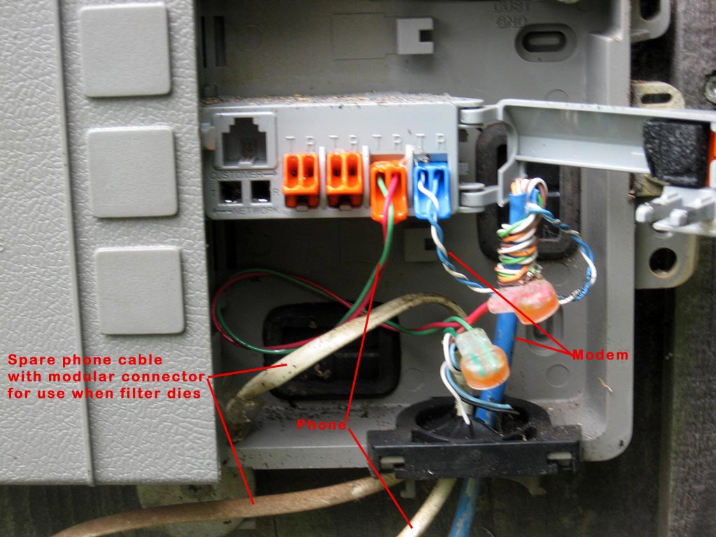
Cover open to show connections. The three orange connections are filtered and meant to be used for normal phones. The blue connection is unfiltered and meant for the modem. The phone line is disconnected from the house-wiring connection tabs when a phone cable is inserted into the modular connector.
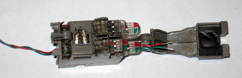
Old filter block that quit working. Red/green wires at left connect to the phone line on the company side of the box. The three connection tabs marked with a green T (tip) and a red R (ring) are for phones. The upper left connection tab is labeled ‘Data.’ A DC ohm meter should read ~0 ohm between the incoming red and the red side of all connection tabs, and also between the incoming green and the green side of all connection tabs. Curiously, this filter block still looks good on a DC ohm meter, but the filter apparently died in such a way that it is blocking or attenuating the DSL signal from the data connection.

Close up of an older filter block with lower left connection tab lifted into position for wires to be inserted. Insert un-stripped wires into the wires holes on the tab, then close the tab to connect the wires.